8 min read
Is the server rack power supply ready for installation?
Check the server rack power supply before installation: load calculations, breakers, cables, phases, grounding, measurements, and acceptance.
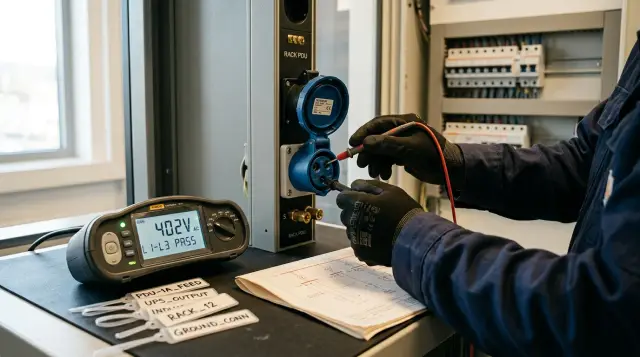
A socket next to the rack does not mean the rack is ready to be powered. Before installation, calculations and measurements must prove that the entire circuit, from the incoming device to every rack PDU, can carry the operating and fault load, disconnect a fault correctly, and maintain the intended redundancy scheme.
I do not accept an electrician saying "there is a 32 amp breaker" without a single-line diagram, cable markings, the breaker's characteristics, and test reports. The rating on the handle says nothing about conductor size, line length, installation method, fault loop, selectivity, or the load on the upstream panel. The mistake appears after the empty rack has been installed, when the servers already support users and shutting them down for rework is difficult.
The procedure below covers the acceptance of a typical server rack in a building with a low-voltage supply. A designer selects the exact conductor sizes, protective devices, and settings under the regulations in force in Kazakhstan, the site's conditions, and equipment manuals. The server-room owner's job is to give the designer complete input data and receive a result that can be verified.
Calculate the load before looking at power-supply ratings
The calculation starts with an equipment list and a realistic operating mode. Adding the maximum wattages printed on power-supply labels usually overstates operating consumption, while readings from idle servers understate it. For each device, you need at least its operating power, expected peak, number of power inputs, and behavior when one input fails.
A server with two 1,600 W power supplies does not automatically impose a 3,200 W load. In normal operation, the supplies may share the actual load, while after one fails, the other must carry it in full. The exact mode depends on the settings and model. Calculate server load with the manufacturer's configurator, telemetry from a comparable configuration, or measurements under a representative computing workload. Use supply ratings to check the upper boundary and connector compatibility, not as the sole basis of the design.
Create a table with a separate row for every consumer. Do not hide switches, KVM equipment, the console, storage, and auxiliary devices inside one "network" row. The same list will help when allocating phases and checking the loss of one input.
| Device | Quantity | Operating power, W | Peak, W | Inputs | Power after a failure |
|---|---|---|---|---|---|
| Compute server | 4 | 650 | 900 | 2 | One input carries 100% |
| Storage system | 1 | 1100 | 1500 | 2 | One input carries 100% |
| Switch | 2 | 180 | 240 | 2 | One input carries 100% |
| Console and KVM | 1 | 70 | 90 | 1 | Through the selected redundant path |
In this teaching example, operating real power is 4 × 650 + 1100 + 2 × 180 + 70 = 4,130 W, while the combined peaks equal 5,670 W. That is not a branch-circuit rating. Add documented growth capacity, account for power factor, UPS efficiency, battery charging, and other loads on the same source. Do not add arbitrary margins at every level. That easily produces an expensive system in which breakers, cables, UPS equipment, and the generator have been sized from four different assumptions.
Keep four figures separate in the document: current load, calculated peak, design load with growth, and installed maximum capacity. Growth capacity must reflect the purchasing plan. If two accelerators with known specifications will be added to the rack next year, include them. "Add another 50 percent just in case" hides a missing decision when there is no scenario behind it.
Eaton's "VA Versus Watts" explanation points out that watts equal volt-amperes multiplied by power factor. Watts and VA cannot be treated as the same number when selecting a UPS or checking current. Obtain the power factor from a manual or measurements across the operating range. A modern server power supply often has a high power factor, but a design should not rest on the word "often."
One input must carry the calculated failure load
An A/B design provides redundancy only when each surviving path can carry the load after the other path fails. If two power supplies share 4 kW equally, each PDU may show about 2 kW. When A is disconnected, the load on B will approach 4 kW. Acceptance testing only in normal operation misses the exact condition that justified buying two inputs.
Draw the route of both inputs back to their sources. Two PDUs plugged into two receptacles on one breaker do not form A/B. Two breakers on one bus section protect against a final branch fault but not a bus-section failure. Two sections downstream of one UPS preserve part of the distribution, yet the UPS remains a common point of failure. The business defines the required degree of independence, and the diagram must show it honestly.
Answer four questions for each path:
- Which failure must it survive: cable, breaker, PDU, UPS, panel section, or utility input?
- What load will transfer to it after that failure?
- Will that load exceed the rating of any connector, PDU, cable, protective device, or source along the route?
- How will an operator know that redundancy has already been lost?
A single-cord device does not become redundant because two PDUs stand nearby. Connect it to a selected path or through a suitable automatic transfer switch that is compatible with the load and sources. That switch also has a current limit and a transfer time. Test the solution with the specific device instead of assuming it works universally.
Schneider Electric's "Rack Powering Options for High Density" examines the number of feeds, single-phase and three-phase power, breakers, connectors, overload, and loss of redundancy separately. It is a useful framework: you cannot choose a connector or PDU apart from the failure mode. I would add a mandatory failure test, because a tidy diagram does not prove that the power supplies and monitoring behave as expected.
Check the transition state. After the missing input returns, server power supplies may begin sharing the load again, the UPS may change modes, and an automatic transfer switch may transfer back. Record currents before the failure, while one path carries the load, and after restoration. If an overload alarm activates during the test or one power supply fails to accept the full load, the rack is not ready.
Select the breaker and cable as one protective circuit
A breaker's rating cannot be assigned from the rack's desired power. The designer first determines design current and load characteristics, then verifies the cable's permissible current with allowances for conductor material, cross-section, temperature, grouped installation, number of loaded conductors, and installation method. The designer then coordinates the protective device with the cable, fault current, and required disconnection time.
For a single-phase load, estimate current as follows:
I = P / (U × PF)
For a balanced three-phase load:
I = P / (√3 × Uline × PF)
These formulas give operating current but do not select a conductor size. They do not account for voltage drop, temperature in the cable tray, several loaded circuits routed together, or the permissible current of a particular cable type. A cross-section table without context is dangerous, so there is no universal answer such as "a rack needs a 6 mm² cable."
Ask the electrician for a calculation showing cable designation, conductor material, cross-section, length, installation method, correction factors, design current, permissible continuous current, voltage drop, expected fault current, and disconnection time. For the breaker, you need its rating, trip characteristic, breaking capacity, and coordination with upstream protection. A page that says only "C32 breaker, 5 × 6 cable" is a specification, not a justification.
The device's breaking capacity must be at least the prospective short-circuit current at its installation point. At the far end of the circuit, however, fault current may be too low to operate the selected trip mechanism quickly. Check both ends: the device must safely interrupt a high current near the panel and disconnect a fault near the rack fast enough.
Selectivity also needs evidence. A fault on the final circuit should preferably trip its own breaker, not the server room's incomer. Compare time-current curves and the manufacturer's selectivity tables for the exact devices. The simple rule that "the upstream rating is twice as large" does not prove selectivity across the full current range.
Coordinate residual-current protection separately. IT equipment, filters, and UPS systems have leakage currents, and currents from several devices add together. An incorrectly selected RCD type or setting can cause unwanted trips, but that does not justify removing the protection without authorization. The designer determines where regulations and equipment manuals require it, which type suits the possible fault-current waveform, and how selectivity will be maintained.
Do not place a household extension lead between a building receptacle and the rack PDU. It adds connections of unknown condition, weakens mechanical retention, and often becomes the weakest component in the circuit. The PDU inlet, mating receptacle, cable, and breaker must form one coordinated system with clear ratings and labels.
Balance phases for the failure scenario
Check phase balance both during normal load sharing and after the loss of an input or equipment group. In a three-phase PDU, single-phase server supplies are distributed among phases. If all the heavy servers land on one phase by accident, the PDU's average value can hide an overloaded conductor.
Create a map of "PDU outlet - device - power supply - phase." Read each phase from a managed or metered PDU. If no telemetry is available, the electrician measures current with a suitable instrument. Take readings under a representative workload, not only while operating systems are starting.
A table in this form makes the allocation easy to review:
| Scenario | L1, A | L2, A | L3, A | N, A | Status |
|---|---|---|---|---|---|
| A and B available | 7.8 | 8.3 | 7.5 | measure | Normal |
| Input A disconnected | 14.9 | 16.1 | 15.2 | measure | Check against design |
| Input B disconnected | 15.4 | 15.7 | 15.0 | measure | Check against design |
These figures only illustrate the report's format. Your system's ratings and the designer's calculation determine acceptability. Improve balance by moving connections, but do not move one of a server's two supplies in a way that leaves both dependent on one phase, breaker, or outlet group.
Do not assume the neutral is unloaded from the classroom diagram of three equal resistors. Switched-mode power supplies create harmonic currents, and triplen harmonics can add in the neutral instead of cancelling. The designer accounts for the load composition and sizes the neutral conductor and equipment accordingly. During acceptance, measuring neutral current at representative and high load is useful, especially when the room contains many single-phase IT consumers.
Eaton describes PDUs with alternating outlet phases as a way to simplify load balancing. The mechanism is useful, but outlet labels do not replace a connection map. An installer can easily connect several high-power units in sequence without understanding the pattern. Record the phase of every outlet in the as-built documents and mark it clearly on the rack.
Save baseline measurements after commissioning the rack. An increase on one phase several months later often comes from an installation that nobody added to the table. Set the monitoring warning threshold below the trip point and connect it to a response procedure. An alarm ignored for months does not protect redundancy.
Verify grounding by instrument and inspection
The rack must have a reliable connection to the building's protective system, and acceptance must confirm continuity of the protective conductors. A wire that visibly disappears under a raised floor proves nothing. The electrician identifies its termination, inspects the connections, and measures the circuit with an established method.
The Electrical Installation Rules of the Republic of Kazakhstan require automatic disconnection for indirect contact in low-voltage systems with a solidly grounded neutral, connection of exposed conductive parts to the protective system, and equipotential bonding. The Rules for Technical Operation of Consumer Electrical Installations also state that every part requiring grounding must be connected by a separate conductor. That restriction matters: you cannot daisy-chain several racks with a thin jumper and assume the first connection solves the problem.
Check these connections:
- the protective contact of each supply connector to the circuit's PE conductor;
- the rack PDU enclosure as required by its manufacturer;
- the main rack frame and doors or removable panels when the construction requires it;
- metal cable trays and other conductive parts according to the design;
- the equipotential bonding bar and its connection to the building system.
Paint, anodizing, dirt, and a loose washer impair contact. Use the specified fasteners, terminals, and tightening torque at factory grounding points. Do not remove paint from an arbitrary part of the enclosure. You can damage its protective coating and still fail to make a stable connection.
Do not build a separate "clean earth" for the servers without a design. An isolated earth electrode next to the common system can create a dangerous potential difference during a fault or lightning event. If equipment requires functional earthing for interference control, the designer coordinates it with protective earthing and equipotential bonding.
One earth-electrode resistance measurement does not answer whether the final circuit is safe. You need data appropriate to the earthing arrangement: PE continuity, fault-loop parameters or another verification of automatic disconnection, operation of protective devices, and condition of the bonding system. The electrician determines the required set from the network diagram.
IEC 60364-6:2016 requires initial verification of a new installation, as well as additions and alterations, through inspection, testing, and reporting. I like that sequence: inspect first to establish that the installation follows the design, then measure it. An instrument will not reveal a bad design concept, while an inspection cannot prove disconnection time.
The supply starts far upstream of the rack
The final circuit can be flawless while the server room still loses power because an upstream floor panel is overloaded, the UPS is undersized, or a common point of failure exists higher in the chain. Before installation, trace the supply to the agreed responsibility boundary and verify the spare capacity of every component.
The single-line diagram should show the building transformer or incoming service, main and intermediate panels, bus sections, protective devices, bypass, UPS, generator, automatic transfer system, final circuits, and PDUs. Record each component's rating and existing load. If the landlord owns part of the infrastructure, request confirmation of allocated capacity and identify where your organization's responsibility begins.
Select a UPS against both watts and VA. Check output power, load power factor, permitted overload, runtime under the calculated scenario, recharge current after discharge, bypass, and manufacturer limitations. A label reading "10 kVA" without the available kilowatts and operating mode does not complete the calculation.
The generator and UPS must be compatible in their dynamic response, frequency range, harmonics, and transition behavior. Starting the generator without load proves only that the engine starts. A planned test should transfer real or equivalent load, observe the UPS, and return to utility power. Specialists plan this test because it affects operating systems.
Surge protective devices must be selected and coordinated within the design, with short connections and appropriate protection. A separately purchased module in the final panel will not repair the absence of an overall lightning and surge-protection concept. Ask the designer which stages exist upstream and how the final stage coordinates with them.
Check cooling as well. Nearly all real power used by the IT load turns into heat in the room, while UPS and distribution losses add more depending on their location. Electrical spare capacity without matching cooling capacity allows servers to be installed only for them to throttle or shut down on temperature later.
For projects using S200 Series servers and other infrastructure, GSE can connect the equipment specification with system integration and data-center infrastructure. The site owner must still accept the electrical installation against calculations, diagrams, and reports rather than matching names in a commercial proposal.
Complete measurements before connecting servers
Before expensive equipment is installed, the electrician completes initial verification of the circuit, reports the results, and corrects nonconformities. The test set depends on the earthing system, design, and local requirements, but "the outlet has 230 volts" is not acceptance.
The program normally includes inspection of installation and labels, continuity of protective conductors, insulation resistance, polarity, phase sequence, fault-loop parameters, operation of automatic disconnection devices, and functional transfer tests. Where RCDs are fitted, test them with a suitable instrument. Measure voltage without load and under an agreed load, phase and neutral currents, and record protective-device settings.
Qualified personnel with appropriate protective equipment and test instruments perform work inside panels and measurements on energized installations. A system administrator should not hold probes on busbars. Their job is to define scenarios, match circuit identifiers, and receive an understandable report.
The test load must represent the design operating mode. An empty PDU draws almost nothing, so it will not reveal heating at a poor connection or significant voltage drop. The electrician selects a safe load and test duration. After conditions stabilize, they check current, voltage, connections, and abnormal heating by the method specified in the work program.
Run functional acceptance with a repeatable sequence:
- Record A and B voltages and currents while the test load operates normally.
- Disconnect path A with the normal switching device under the approved procedure and confirm that every designated consumer remains powered through B.
- Record phase currents, voltage, and alarms from the UPS, PDU, and server power supplies or their equivalent.
- Restore A, wait for stable operation, and repeat the actions for loss of B.
- If the design includes a UPS, bypass, generator, or automatic transfer system, test the permitted transitions separately and retain the event log.
Do not simulate a failure by pulling a plug under load unless the connector and instructions permit that operation. Use the normal switching device and an agreed procedure. Define success in advance: which devices must not restart, what interruption time is allowed, which alarms must appear, and which current values are acceptable.
Keep actual values, instrument model, date, circuit identifier, and test conditions, not only a final "pass." A year later, the data will help distinguish a normal load change from a deteriorating connection or unauthorized alteration.
Documents must match the labels on site
Accept the rack against a package in which every device and cable can be matched unambiguously to the diagram and report. If a breaker says "Server 1," the receptacle says "R-07," and the diagram says "Panel 2 circuit 14," finding the correct disconnect during an incident becomes an experiment.
Request the as-built single-line diagram, cable schedule, route plan, device and connector specification, load and fault-current calculations, test reports, UPS and protection settings, switching instructions, and a defect list with closure records. For a leased site, attach the letter confirming allocated capacity and the responsibility boundary.
Labels must match at both cable ends, on the breaker, receptacle, PDU, and in the documents. Use a durable color or letter distinction for A and B, but do not rely on color alone. A person with impaired color vision and a photograph taken in poor light must preserve the meaning.
Check document revisions. A design diagram produced before installation does not replace an as-built diagram after the circuit has been moved to another breaker. Pencil corrections are acceptable on a working copy during installation, but acceptance documents must include the changes in a controlled revision with a date and responsible person.
Every setting needs an owner. If a breaker, UPS, or PDU allows threshold configuration, record the value, rationale, and permission to change it. A factory password or an unknown contractor account creates an operating problem after handover even when the power installation is correct.
Photograph the panel and connection points after completion, while labels remain readable and access has not been blocked by other cables. Photographs help maintenance but do not replace the report and diagram. They contain no design current, concealed cable length, or fault-loop measurement.
Acceptance ends with a controlled power-up
Authorize installation only after calculations, inspection, measurements, failure tests, and documentation are complete. One release sheet with references to the evidence works better than ten independent email threads in which everyone assumes someone else performed the check.
The minimum release sheet should answer "yes" to these questions:
- has the equipment list, operating power, peak, and growth been agreed;
- can each path carry the intended load after the other fails;
- are cables, breakers, connectors, PDUs, UPS equipment, and the upstream supply coordinated;
- are phases allocated and neutral current verified in the required modes;
- have measurements confirmed protective conductors and automatic disconnection.
Attach report numbers, the diagram, and open defects to the sheet. "Add a label later" is not the same as "PE continuity has not been confirmed." The first can be assessed as an administrative debt, while the second blocks safe energization. Define authority to accept residual risk in advance, and do not make the electrical contractor decide the business risk of downtime alone.
Follow a plan for the first power-up. Connect equipment in groups, watch the currents on each phase and both paths, and compare readings with the calculation. After reaching the operating load, capture the parameters again and save them as a baseline. If actual values differ materially from the calculation, stop and find the cause before filling the rack.
Schedule re-verification after configuration changes. A new server, accelerator, PDU, or move between outlets changes the inputs. Major changes need an engineering review; minor ones need a working process for capacity and phase records. The rack stops matching the accepted design the moment the team changes load without recording it.
Good acceptance leaves a chain of evidence instead of an electrician's promise: the calculation explains the selection, the diagram shows the path, labels connect documents to equipment, measurements verify protection, and the failure test checks the operating scenario. Delay server installation while any link in that chain is missing.
Frequently asked questions
How do I calculate server rack consumption before buying equipment?
List every device with its operating power, peak, number of inputs, and failure behavior. Use manufacturer configurators or measurements from a comparable configuration, then add documented growth, UPS losses, and battery charging separately.
Should I add the ratings of a server's two power supplies?
Usually not: two supplies often share the actual load or provide redundancy rather than create two separate loads. Each remaining input must still carry the whole server after the other fails, so verify the mode of the specific model.
Which breaker does a server rack need?
You cannot choose it from rack kilowatts alone. An electrician coordinates the rating, trip characteristic, and breaking capacity with design current, the cable, fault currents, disconnection time, and upstream protection.
Which cable size is suitable for a 32 A rack?
There is no universal size. The choice depends on cable material and type, length, temperature, installation and grouping method, number of loaded conductors, voltage drop, and protective-device operating conditions.
Can I connect a rack PDU through a household extension lead?
Do not use one for a permanent installation. It adds weak, poorly controlled connections, while the PDU inlet, receptacle, circuit, and breaker need coordinated ratings and secure retention.
Does a server rack need a separate earth connection?
Connect the rack to the protective system and equipotential bonding as specified by the design and manufacturer. A separate isolated earth electrode without a design can create a dangerous potential difference and does not replace a sound PE conductor.
How do I check phase balance in a three-phase PDU?
Map the outlets and measure each phase under a representative workload. Repeat the measurement after simulating loss of A and B, because normal balance may disappear when one path takes the full load.
Is checking outlet voltage with a multimeter enough?
No. The presence of voltage does not verify PE continuity, insulation resistance, polarity, fault-loop parameters, protective-device operation, or voltage drop under load.
Which documents should the electrician hand over after installation?
You need the as-built single-line diagram, cable schedule, calculations, device specification, test reports, protection settings, and switching instructions. Document identifiers must match the labels on breakers, cables, receptacles, and PDUs.
When can servers be installed in a new rack?
Only after calculations, inspection, measurements, and functional tests of both paths in normal and failure modes are complete. An open defect involving the protective conductor or automatic disconnection blocks energization even if the mechanical work is finished.