8 min read
A 40 kW rack in an existing server room
A 40 kW rack needs a new power feed, local cooling, a floor check, and isolated airflow. See the retrofit scope and budget.
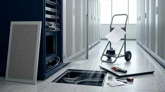
You cannot add a rack with a 40 kW IT load to an existing server room as if it were one more cabinet. It changes the electrical design, heat balance, room aerodynamics, and load on the building structure. If any one of those systems stays unchanged, the rack will either fail to reach its design capacity or consume the resilience reserved for neighboring equipment.
The right start to this project looks unusual for a server purchase. Engineers first measure what the building can support, then choose the power and heat-rejection architecture, and only then approve the rack configuration. A cooling unit or UPS nameplate usually describes the whole system. A high-density rack needs guaranteed capacity at its exact location and after one component fails.
Forty kilowatts turn a cabinet into a facilities project
Base the design on actual IT power, the load profile, and availability requirements, not the sum of power-supply nameplates. A server with two 2 kW supplies does not consume 4 kW. The second supply usually shares the load or backs up the first. The opposite mistake is more dangerous: a project uses monthly average consumption and misses short peaks from compute work, accelerators, and fans.
Ask the equipment supplier for four data sets at the outset: maximum input power for the selected configuration, typical power on your workload, air or liquid flow, and the mass of the complete assembly. You need values for the chosen inlet temperature and for a fan or power-supply failure mode. A general label saying "up to 40 kW" gives the designer no usable inputs.
Projects often blur a distinction that deserves sharp wording. "The rack is rated for 40 kW" means the cabinet, busbars, and PDUs can accept it. "The server room supports a 40 kW rack" means the electrical system, cooling, floor, fire controls, and monitoring can carry that load together. A catalog can confirm the first claim. The design and an integrated test must confirm the second.
Intel has described a converted high-density facility where air cooling supported racks up to 43 kW. That example disproves the categorical claim that air becomes useless above 30 kW. It proves a narrower point: air can handle 40 kW in a room designed around high flow and prevention of air mixing. It does not make an ordinary room with wall-mounted split systems suitable.
Before design begins, build a profile with at least three states: normal load, design maximum, and growth during the next expansion cycle. Define the response to a failure separately. If losing one module permits a temporary compute cap at 28 kW, that can be a valid engineering choice, but the limiting automation must exist and be testable. "Operators will reduce the load in time" is not redundancy.
The survey must distinguish installed capacity from available capacity. Record the nameplates, then set beside them power-analyzer readings and trends covering at least a representative load cycle. For cooling, log the unit model as well as actual supply and return temperatures, valve positions, fan speeds, and controller alarms. An empty breaker slot, an open UPS slot, or unused floor area can look like reserve even when each depends on a shared upstream component that has no headroom.
Check the physical layout too. A deep rack with two vertical PDUs, cable managers, and a rear-door heat exchanger needs clearance for the doors, power-cable bend radius, and extraction of a server on its rails. A narrow hot aisle can make service unsafe or obstruct the exhaust. A floor plan with a 600 by 1,200 mm rectangle does not reveal those conflicts, so the engineer must draw work zones and the removal path for the longest component.
Trace the power feed back to its source
A 40 kW rack needs a three-phase feed with headroom for continuous load, losses, and growth. At 400 V line voltage and a power factor of 0.95, current can be estimated as follows:
I = P / (√3 × U × cos φ)
I = 40 000 / (1,732 × 400 × 0,95) ≈ 61 А
Those 61 A are not a ready-made breaker rating. The electrical designer must check local code, permitted continuous loading of the device, cable installation method and temperature, protective-device selectivity, short-circuit current, harmonics, and phase imbalance. In practice, the rack feed often falls into the 80 A class or above, but copying that rating into a design without calculations is unsafe.
The project boundary does not stop at the rack receptacle. Check the chain from the building connection point: transformer, main switchboard, generator, automatic transfer switch, UPS, bypass, room distribution board, cable, and both rack PDUs. An apparent 50 kW of UPS headroom is useless if the bypass, generator, or feeder cable is already loaded. A new cable cannot fix an undersized transformer either.
For a dual-path A/B design, size each path for the load it takes after the other path fails. Under normal 50/50 sharing, one path carries about 20 kW, but it must safely accept all 40 kW after its neighbor fails unless the servers enforce a power cap. Two 25 kW feeders therefore do not create a redundant 40 kW system.
Eaton's power distribution guide distinguishes a floor-standing distribution PDU from a rack PDU. The first brings power into the room and distributes it, while the second provides monitored outlets to equipment. The layers are not interchangeable. At this density, you need current measurements by phase and path, threshold alerts, clear outlet numbering, and secured plugs. Without them, a small server move can overload one phase while the rack total remains below 40 kW.
Do not select a UPS by kVA alone. Compare active power in kW, power factor, permitted step loads, generator compatibility, runtime at design load, and battery-area temperature. If the current UPS already serves the room, adding 40 kW may force replacement of its modules, battery cabinets, bypass, and input feed at once. Modular growth helps only when the chassis, switching, and cooling had enough capacity from the start.
Remove the heat where it is produced
A rack consuming 40 kW releases almost all of that 40 kW into the environment as heat. That is about 136,500 BTU/h or 11.4 tons of refrigeration before UPS and PDU losses, cooling-unit fans, lighting, and heat gains through the room envelope. "The room has a 40 kW air conditioner" therefore does not mean "40 kW of cooling is available to the rack."
Adjust nameplate cooling capacity to the design conditions. Air temperature and humidity, outdoor temperature, line length and elevation change, water temperature, heat-exchanger flow, and dirty filters can all change it. Then add control margin and settle the resilience requirement. Two 20 kW units cover the load only while both operate. After one fails, half the required cooling remains.
The sensible-heat equation published by ASHRAE gives a useful first estimate for an air circuit:
Q = P / (ρ × cp × ΔT)
Q = 40 000 / (1,2 × 1 000 × 12) ≈ 2,78 м³/с
2,78 м³/с ≈ 10 000 м³/ч
The calculation assumes air density of 1.2 kg/m³, specific heat of 1,000 J/(kg·K), and a 12 °C temperature rise through the rack. At a 10 °C rise, the requirement grows to about 12,000 m³/h. Lower air density at high elevation increases the volumetric flow. Use the server documentation for the final value because built-in fans change their flow with load and temperature.
ASHRAE TC 9.9 gives a recommended inlet-temperature range of 18-27 °C for typical server equipment. "Inlet" matters more here than the limits themselves. A cooling sensor near the ceiling can report 23 °C while the top servers receive 31 °C because of recirculation. Put sensors at the lower, middle, and upper front face of the rack, and monitor exhaust temperature and differential pressure as well.
Ordinary comfort split systems are a poor fit for more than their limited capacity. They may not maintain the required flow around the clock, control humidity, retain output during winter or summer extremes, or coordinate as an N+1 group. They can remain for the room's background load, but tie the 40 kW rack to a local circuit: in-row units, a rear-door heat exchanger, a ducted hot-air return, or liquid near the heat source.
The outdoor heat-rejection location is part of the design too. An outdoor condenser or dry cooler must operate at the design summer temperature, avoid drawing in its own hot discharge, and remain accessible for cleaning. Check noise at occupied boundaries and vibration through the structure. If the route crosses occupied floors or the facade, permits and building work may take longer than the installation inside the server room.
Cold and hot air cannot share one undivided room
At roughly 10,000 m³/h, any short airflow path causes overheating. Cold air that bypasses the servers and returns straight to the cooling unit lowers return temperature and usable coil capacity. Hot exhaust that reaches the front of the rack raises inlet temperature. A room thermometer averages both errors and can show a reassuring number.
First decide which side to contain, cold or hot. In an existing small server room, it is often easier to enclose the hot side of the rack and send the exhaust straight back to the cooling unit. If the room cannot accept a sealed aisle, an air-to-liquid rear door or a cabinet with an overhead exhaust duct can create a local boundary.
Details decide whether the named architecture works. Fit blanking panels in every open rack unit, seal gaps around cables and under the rack, verify the fan direction of network switches, and move cable coils out of the exhaust path. Schneider Electric's aisle-containment material discusses bypass and recirculation directly. I agree with the principle, but one aisle door cannot fix inadequate flow through perforated tiles or a switch facing the wrong direction.
A raised floor is optional. It helps when the plenum is tall enough, cables do not obstruct its free area, openings are sealed, and tiles deliver the required flow at the available pressure. Several standard perforated tiles can become the bottleneck for one 40 kW rack. Do not swap in tiles with more open area blindly. That change rebalances the whole room and can take air away from neighboring racks.
Test the arrangement under heat load, not with a smoke pencil in an empty cabinet. Smoke shows direction at one moment, but not inlet temperature with server fans at full flow. A thermal map with nine points on the rack front, a flow or pressure measurement, and supply and return temperatures give a much more honest picture.
Check the floor by mass and support reactions
Forty electrical kilowatts say nothing about floor load. Two cabinets with the same power can differ twofold in mass because of accelerators, storage, copper busbars, cables, and liquid manifolds. The structural engineer needs a mass schedule, center-of-gravity layout, and support geometry for the complete rack.
Calculating only average kg/m² is dangerous. A rack transfers weight through four adjustable feet or casters, and a raised floor passes it through tiles, stringers, and pedestals. The review must cover the building slab, point reaction, local punching, raised-floor tile rating, and cabinet stability. A steel spreader frame can distribute the force across several pedestals, but an engineer must calculate that frame rather than choose its thickness by eye.
Do not confuse cabinet load capacity with floor capacity. A UL 2416 cabinet test confirms that the frame carries its declared static mass and remains stable during the specified tests. It says nothing about the particular floor slab in your building. The rack certificate and the structural engineer's report answer different questions.
The delivery route belongs in the same calculation. Check elevator capacity, thresholds, door widths, turning radius, ramp gradient, and temporary loading from a transport dolly. A fully assembled rack may be impossible to move safely even when its final position is reinforced. In that case, crews bring heavy components in separately and assemble them in place under an approved sequence.
Include PDUs, cables, heat-exchanger doors, distribution manifolds, and liquid in the total mass. Leave an installation allowance: an extended server, a lifting device, and two technicians may all stand beside the rack during work. The structural part of the design sets seismic restraint and anchoring for the site; the cabinet manual does not.
Redundancy without independent paths only looks resilient
Higher density raises the cost of a common failure, so draw the route to the physical source of each path. Two rack PDUs connected to one board protect against one PDU failure, but not against a shared breaker, cable, board, or upstream UPS. Two cooling units on one breaker have the same weakness.
On the single-line diagram, mark A and B in different colors from each server power supply back to the transformer or another agreed boundary. Then find every place where the paths meet: a shared building input, transfer switch, generator, bypass, control system, or fuel system. Full independence is expensive and not every operator needs it, but common failure points must be an owner decision rather than an accident discovered during an outage.
Calculate cooling redundancy after one unit is lost under adverse outdoor conditions. N+1 works only when the remaining units actually remove 40 kW and maintain the required rack airflow. One spare compressor does not help after a shared pump, dry cooler, controller, or pipe fails. A liquid design needs the same review for the CDU, pumps, filters, valves, and controls power.
Transient behavior matters too. When cooling stops, inlet temperature in a dense rack rises faster than in a room with average loads. The controls must detect failure early, start the reserve, and cap IT power if needed. Match alarm setpoints to the room's thermal inertia and startup time, then test them. An audible alarm that only a technician in another building might hear is not protection.
Review the fire system as well. A new cabinet and containment alter smoke movement, detector locations, and the discharge of extinguishing agent. After power cables are installed, restore penetrations with a system carrying the required fire rating. If water or a water solution runs near the rack, define leak detection, isolation valves, a tray or drain, and a shutdown sequence that avoids a dangerous common stop.
Acceptance must prove capacity, not equipment presence
Before installing servers, survey the live room under load. Capture daily trends for power, phase currents, temperature, and cooling state, verify the single-line diagrams in the field, and record spare breakers, cable sizes, and equipment models. Correct any mismatch between labels and diagrams before connecting the new rack.
After the retrofit, run an integrated test with controllable load banks. Servers are poor tools for the first check: they produce uneven loads, may trip into protection, and put data at risk. A practical sequence has five stages:
- Apply 10, 20, 30, and 40 kW in steps, holding each step until temperatures stabilize.
- At every step, record A/B current by phase, voltage, power, inlet temperature at nine points, and the state of all cooling units.
- At 40 kW, disconnect in turn one feeder, UPS module, cooling unit, and each control component claimed as redundant.
- Verify alarms, automatic transfer, power limiting, and recovery without concealed manual actions.
- Repeat the critical tests on generator power if the generator is part of the availability path.
Set acceptance criteria before the test. They include permitted inlet temperature, maximum loading of phases and devices, transfer time, absence of condensation and leaks, pressure retention, and reserve startup time. The deliverables should include trend records, updated as-built diagrams, setpoints, and an exception list. A contractor's statement that "it all holds" has no operational value.
Do not skip partial load. Some cooling units regulate poorly at low output, air balance changes with server-fan speed, and a modular UPS runs at a different efficiency. The rack will not live only at the 40 kW point, so test its normal state and transitions between states.
Retrofit budgets start at roughly KZT 70 million
For one rack, a sensible preliminary budget is KZT 70-190 million, excluding the servers, an external transformer, a new generator, and major structural reinforcement. This is not a commercial quote. The range identifies the class of project before the survey; it should not approve a purchase at an average figure.
The budget breaks into five work packages:
- survey, detailed design, and acceptance testing: KZT 6-16 million;
- feed, boards, cables, and A/B paths: KZT 8-25 million;
- 60 kW UPS, batteries, and bypass: KZT 18-45 million;
- local cooling with reserve: KZT 25-70 million;
- rack, air containment, floor, fire work, and monitoring: KZT 10-30 million.
The condition of existing drawings, structural calculations, and number of failure scenarios affect the first package most. Cable-route length, selectivity, and replacement of the main board control electrical cost. UPS autonomy and module reserve matter, as do the outdoor circuit and N+1 arrangement for cooling. Structural reinforcement, heat-exchanger doors, sensors, and restored penetrations make the final package more expensive.
Public prices provide a useful order-of-magnitude check. In Kazakhstan, supplier listings put a three-phase 60 kVA UPS, before a project-specific battery runtime is included, at roughly KZT 19 million. A National Bank procurement allocated about KZT 43.9 million for two precision cooling units with removal, installation, and commissioning. You cannot add those items and call the result a project price because the required resilience, routes, outdoor conditions, and scope are unknown. They do show why a promise to retrofit this room for a few million tenge does not survive scrutiny.
Three scenarios make the broad range easier to use. If spare UPS modules, prepared A/B routes, a strong floor, and space for local cooling already exist, the project may stay near the lower bound. A new UPS, two cooling units, air containment, and switchboard work move it toward the middle. A new transformer, generator, floor reinforcement, or outdoor liquid circuit takes the project above KZT 190 million.
Calculate ownership cost, but do not guess from PUE alone. Request cooling-unit electrical demand at the design outdoor temperature, UPS losses at normal and peak load, filter and battery service, pump life, water consumption, and the cost of required inspections. A cheap unit that forces a full rack shutdown for service can become the most expensive option over several years.
Set a contingency after the survey. Before routes are opened, 15-25 percent is reasonable because live server rooms reveal occupied pathways, unlabelled cables, unsealed penetrations, and inaccurate as-built drawings. The uncertainty should shrink after detailed design. If it does not, the design is not finished.
Server configuration decides between air and liquid
At 40 kW, air cooling remains possible, but it needs roughly 10,000-12,000 m³/h of directed flow and a well-contained return path. If the chosen servers are entirely air cooled, local in-row units or an air-to-liquid rear-door heat exchanger may be simpler than changing the compute nodes. Verify the choice against manufacturer airflow maps and a full-rack test.
Direct liquid cooling makes sense when the servers are designed to transfer a substantial share of their heat to liquid, density will rise, or the room cannot pass the required volume of air. It does not remove the heat problem. It moves that problem into the CDU, pipework, and outdoor circuit. Memory, storage, power supplies, and network gear still release residual heat, so a smaller air circuit normally remains necessary.
Reject the advice to "install liquid immediately because 40 kW is a lot." It is popular because AI loads are growing, but a rack power figure does not define the cooling interface. First learn what share of heat the selected configuration sends to liquid, the temperatures and flows it requires, who owns water quality, and whether the warranty accepts the chosen connections. Without those answers, liquid cooling adds pumps and leak risk without cooling every component.
GSE.kz can connect server selection, data center infrastructure, and ongoing support in one project, which is especially useful at the boundary between IT and building operations. Whatever the contractor structure, the owner needs one agreed model for power, heat, and failures instead of three unrelated paper reserves.
Approve the retrofit only after four signed results exist: measured available power, a thermal concept with a failure state, a structural report, and a detailed-design estimate. If any one is missing, the 40 kW rack exists only in the server specification. It is too early to energize it in a live room.
Frequently asked questions
Can you install a 40 kW rack in a normal server room?
Sometimes, but empty space in the room proves nothing. You need confirmed headroom in the power feed, UPS, cooling, floor, and resilience, measured for that local zone rather than inferred from room averages.
How much current does a 40 kW rack need?
At 400 V, three phases, and a power factor of 0.95, the calculated current is about 61 A. The designer must add headroom and account for continuous operation, startup behavior, harmonics, and local code, so this figure alone cannot set the protective-device rating.
How much cooling does a 40 kW rack require?
At least 40 kW of sensible cooling capacity at the design conditions, because almost all IT power becomes heat. The final calculation also includes power-system losses, control margin, outdoor temperature, and cooling redundancy.
Are two 20 kW air conditioners enough?
No, if losing one leaves only 20 kW of cooling against a 40 kW load. That pair provides total capacity but no N+1 reserve, and each nominal 20 kW rating still needs verification at the actual temperatures and pipe lengths.
Is liquid cooling mandatory at 40 kW per rack?
No. A directed air circuit with local cooling units can remove that load. Liquid becomes more sensible when the servers transfer a large share of heat to it, the room cannot fit the air equipment, or rack density will keep rising.
Do high-density racks require a raised floor?
No. Cold air can arrive overhead, from the side, or through in-row units. A raised floor only helps when its height, sealing, and free area deliver the required airflow and its tiles and supports carry the load.
How do you check whether the floor can hold a heavy rack?
Add the cabinet, servers, cables, PDUs, and temporary installation loads, then give the support layout to the building structural engineer. They must check the structural slab, raised floor, point reactions, delivery route, and any required load-spreading frame.
Do you need two independent A and B feeds?
That is the normal arrangement for equipment with dual power supplies if both paths remain independent back to the source. Two PDUs connected to one breaker or one UPS simplify connections but do not protect against a shared failure.
How much does a server room retrofit for one 40 kW rack cost?
For early budgeting, allow roughly KZT 70-190 million, excluding servers, an external transformer, and a generator. The range can change sharply after the survey if the project needs structural reinforcement, new outdoor cooling equipment, pipework, or replacement of shared infrastructure.
What tests should run before the servers are installed?
Apply a stepped simulated load, record current on every phase, measure rack inlet temperature at three heights and check differential pressure, then simulate the loss of every redundant component. The acceptance record needs trends and alarm setpoints, not one photograph of a thermometer.